Lidar System
Device Overview
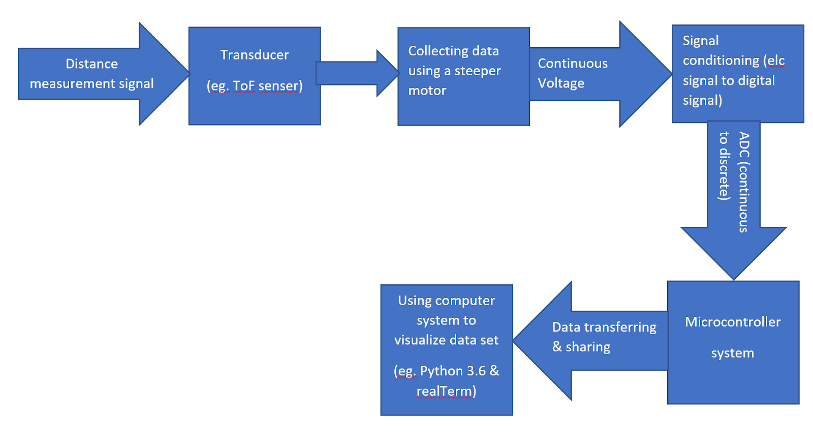
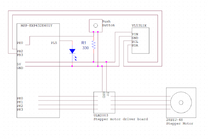
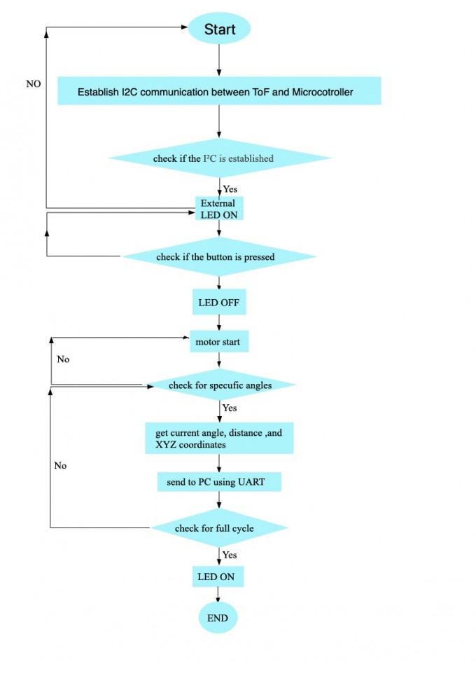
The Time of Flight sensor is the core part of this system, it collects the distance data by taking a 360 degree measurement. The ToF is assembled on the slip ring which allows the ToF rotating freely. A stepper motor is used to drive the slip ring by gears. An external LED is used for status indication and a push button is used to start the measurement.
By pushing the button, the stepper motor will automatically drive the ToF, after taking a 360 degree measurement, it will stop and a 3D visualized graph will pop up on the PC.
Key parts of the application
- ToF module: ST VL53L1X with 940 nm invisible laser
- Microcontroller: Texas Instruments SimpleLink™ Ethernet MSP432E401Y MCU Launchpad™
- Stepper motor: 28BYJ-48
- Stepper motor driver board: ULN2003
- Python 3.6.8 with pyserial and Open3D library
Device Characteristics Table
| Operating voltage | 5.0V |
| Max ranging distance | 400mm |
| Operating Temperature | -20°C ~ 85°C |
| Avg time needed for a single measurement | 21s |
| Total measurement points | 296 |
| Bus speed | 24MHz |
| Baud rate | 115200 |
| Max ranging frequency | 50Hz |
| ADC sampling ratey | 48Hz |
Detailed Description
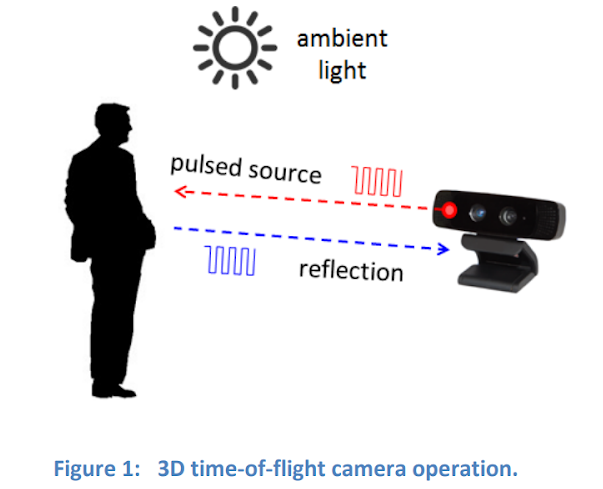
A 3D time-of-flight (TOF) camera works by illuminating the scene with a modulated light source,and observing the reflected light (Figure 1). The phase shift between the illumination and the reflection is measured and translated to distance. For VL53L1X, it measures the absolute distance by using the formula Δd = v*t.
The farthest distance it can measure is around 400mm as it may be affected by ambient light. The VL53L1X can be configured and its distance data can be obtained through I²C bus the SCL and SDA lines on the ToF allows the I²C to communicate with MSP432E401Y microcontroller. To construct a point cloud system, a stepper motor will drive the ToF to do a full cycle rotation to gather the distance data, and those data will be stored in A/D, processed to coordinates and sent to a PC for visualization. To convert distance into coordinates, the current angle will be calculated first and use trigonometric to get the related coordinates. Define current angle (α), current step (n), total step (m), distance (d). X component (x) and Y component (y) can be calculated by:
1 | |
For example, if the current step is 256, total step is 512, distance measured is 200.00mm. Then,
1 | |
So the X component is 0 and the Y component is -200.00mm.
Circuit Schematic
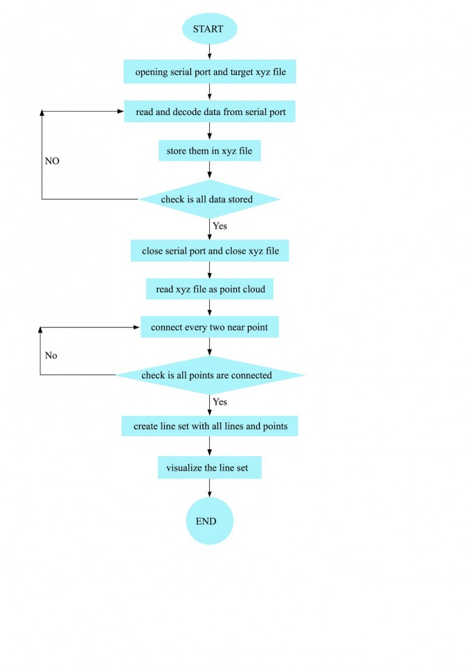
Logic Flowchart
Microcontroller
Python